What Exactly Is a Draw Latch—and Why Is It Different from a Toggle Latch?
You have probably closed a flight case, a toolbox, or an industrial cabinet hundreds of times without giving the latch a second thought. Push the lever down, feel the hook grab the strike plate, and the lid is sealed tight. That simple action is the work of a draw latch—one of the most widely used closure mechanisms in transit case and equipment hardware. Yet many buyers confuse draw latches with toggle latches, choose the wrong material for their environment, or install them in ways that undermine the clamping force they depend on.
The distinction matters. A draw latch that rusts on a marine transport box, a latch that vibrates loose on a food-processing machine, or a key-lock model that fails to hold a power distribution cabinet closed—each traces back to a mismatch between latch type, material, and application. Understanding how draw latches work, what types are available, and how to specify the right one prevents equipment damage, safety incidents, and costly field replacements.
This guide covers the mechanism behind draw latches, breaks down the four major types, compares draw latches with toggle latches, and provides a practical selection framework grounded in NRH Box Hardware catalog data.
What Is a Draw Latch? Definition and Mechanism
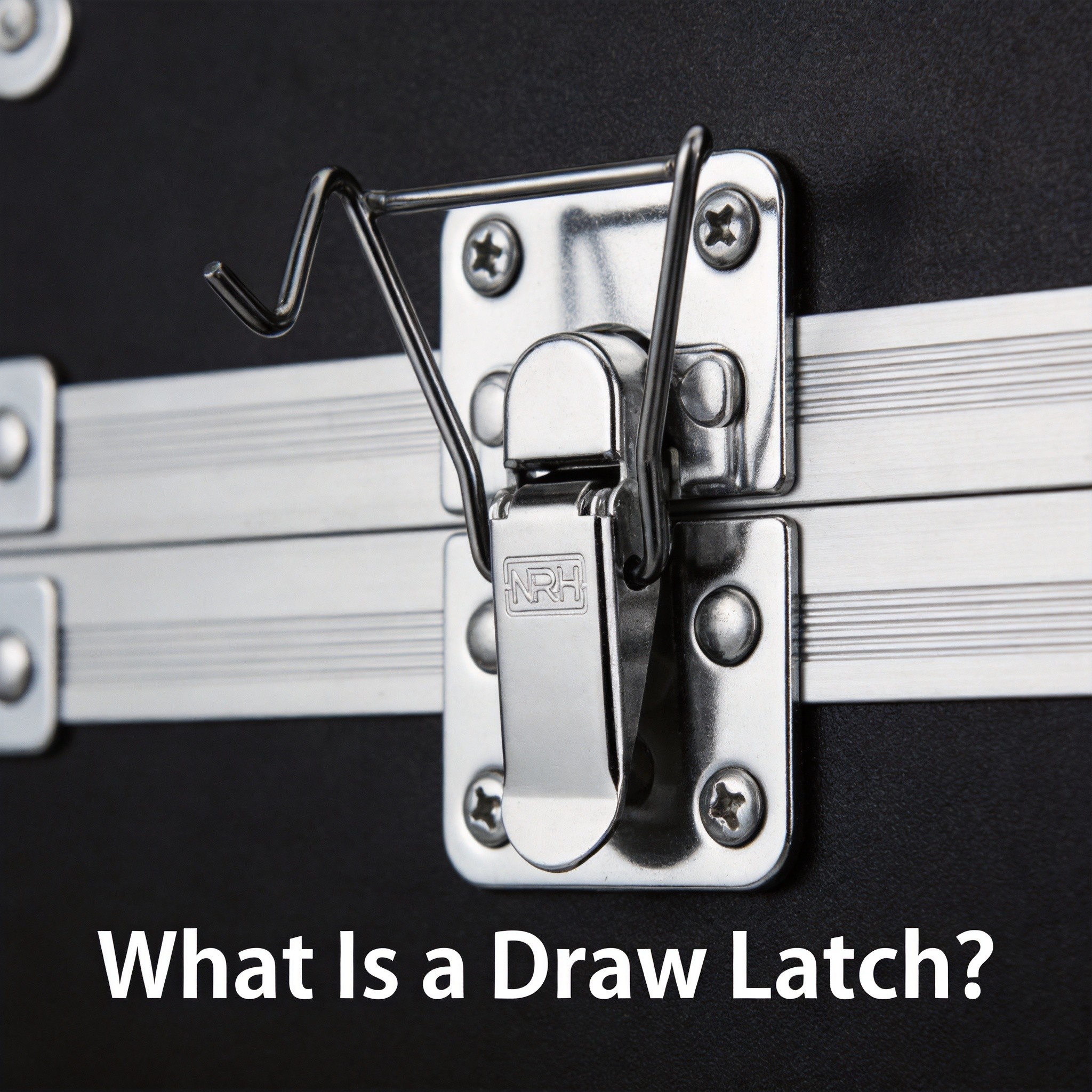
A draw latch is a mechanical fastening device that closes and secures a lid, door, or panel by pulling two surfaces together through a hook-and-strike engagement. The name “draw” comes directly due to the drawing action: when the operator presses the lever arm down, a hook claw rotates inward and catches a fixed strike plate (also called a catch or keeper), simultaneously pulling the lid toward the base and creating clamping force that holds the closure tight.
Hook-and-Strike Engagement Explained
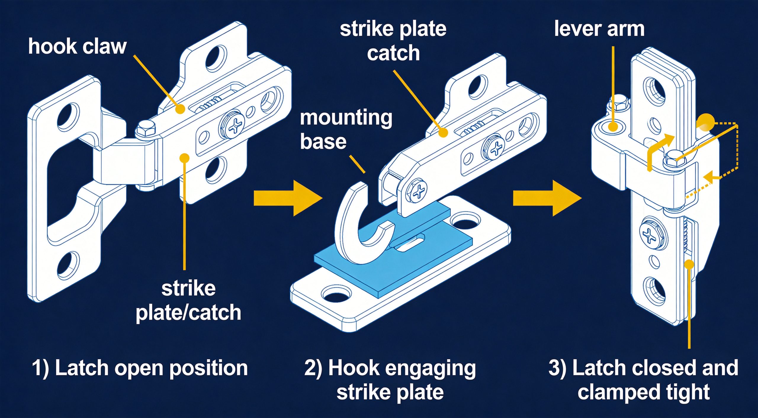
The fundamental operating principle involves three components working in sequence:
- The hook (claw): A curved metal finger attached to the lever arm. As the lever is depressed, the hook rotates around its pivot point and sweeps toward the strike plate.
- The strike plate (catch): A fixed bracket mounted on the opposing surface (typically the case base or frame). The strike plate presents a crossbar or lip for the hook to grab.
- The lever arm: The handle the operator presses. The lever’s geometry creates a mechanical advantage that multiplies the operator’s input force into a much stronger clamping force at the hook-strike interface.
When the lever reaches its fully closed position, the hook is past the strike plate’s crossbar and clamping force holds both parts rigidly. To open, the operator lifts the lever, the hook rotates clear of the strike plate, and clamping force releases. The over-center geometry ensures the latch remains closed under vibration and shock unless deliberately opened.
Draw Latch Types: Standard, Adjustable, Safety, and Heavy-Duty
Not all draw latches work the same way. The four primary categories differ in construction, clamping mechanism, and intended application.
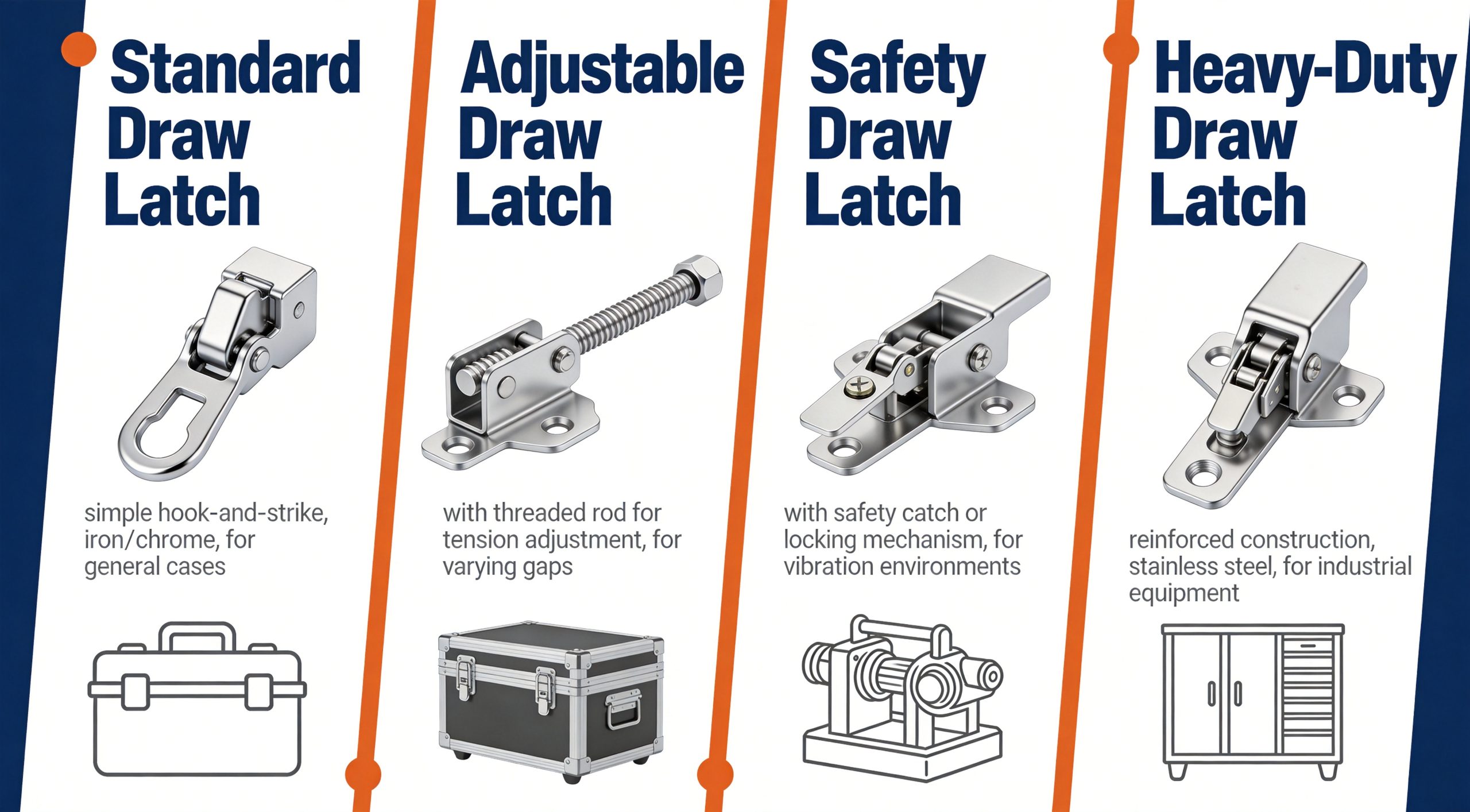
1. Standard Draw Latch
The standard draw latch uses a fixed hook-and-strike pair with a rigid lever arm. It provides straightforward closure for cases and enclosures where the gap between lid and base is consistent and vibration is moderate. The 5403-83-FE-CL is a typical example: an 83 mm iron draw latch with chrome plating, commonly specified at 18 units per wooden freight case to distribute clamping force along a long lid seam, per manufacturer catalog data. Standard latches are the most economical option but do not accommodate variable gap distances and offer no secondary locking mechanism.
2. Adjustable Draw Latch
Adjustable draw latches incorporate a threaded rod that lets the operator fine-tune the clamping distance, compensating for gasket compression, thermal expansion, or manufacturing tolerances. The 5808-128S-S04-ZG exemplifies this category: a 128 mm SUS304 adjustable draw latch with vibratory finish, specified on iron transport boxes where the lid-to-base gap may vary by several millimeters depending on load, per manufacturer catalog data. As the gasket ages and compresses, the adjustable latch can be tightened to restore the original seal pressure.
3. Safety Draw Latch (with Lock)
Safety draw latches add a secondary retention feature—typically a key lock or safety catch that prevents the lever from opening accidentally. The 5101-96K-S04-ZG is a toggle/draw latch with key lock in SUS304, designed for enclosures where unauthorized access or inadvertent opening poses a safety or security risk, per manufacturer catalog data. The 5103-63K-S04-ZG is a compact variant with key lock, commonly specified on power distribution boxes where electrical safety regulations require a lockable closure.
The key lock mechanism engages a deadbolt or locking pin that physically prevents the lever from being lifted, regardless of vibration or shock—essential on electrical cabinets, chemical storage enclosures, and any application governed by access-control requirements.
4. Heavy-Duty Draw Latch
Heavy-duty draw latches are built with reinforced bodies, thicker hook sections, and higher-grade materials for extreme clamping forces and harsh environments. They are typically manufactured in SUS304 with vibratory finish (ZG), which delivers 500+ hours of ASTM B117 salt spray resistance per manufacturer catalog data. The 5101-96-S04-ZG toggle/draw latch falls into this category, specified on food processing equipment where frequent washdowns and strict hygiene standards demand a robust, corrosion-resistant closure, per manufacturer catalog data. Specific clamping force values vary by material and specification; contact the manufacturer for rated values.
How Draw Latches Work: Step by Step
Understanding the operating sequence helps with specification and troubleshooting:
Closing Sequence
- Position the lever: The lever arm is raised (open). The hook is rotated clear of the strike plate, and the gap between lid and base is unclamped.
- Engage the hook: As the operator presses the lever down, the hook rotates around its pivot and sweeps toward the strike plate. The tip passes over the crossbar.
- Draw and clamp: Continued lever rotation pulls the hook downward, drawing the lid toward the base. Clamping force increases as the lever approaches its over-center position.
- Lock over-center: The lever passes through the over-center point. At this position, any force trying to push the lid open actually pushes the lever further into its locked position. The latch is now mechanically held closed without external force.
Opening Sequence
- Lift the lever: The operator lifts the lever past the over-center point. The mechanical advantage reverses.
- Release the hook: The hook rotates clear of the strike plate crossbar, releasing clamping force.
- Disengage: The hook clears the strike plate entirely, and the lid is free to open.
A typical draw latch generates a clamping force 3–5 times the force applied to the lever, due to the mechanical advantage of the over-center linkage. Specific clamping force values vary by material and specification; contact the manufacturer for rated values. On adjustable models like the 5808-128S-S04-ZG, the effective reach of the hook can be changed: more threads engaged increases pre-load on the gasket, fewer threads reduces it—allowing the operator to restore optimal gasket compression as the seal ages.
Draw Latch vs. Toggle Latch: When to Use Which
Draw latches and toggle latches are frequently confused because both use a lever-actuated over-center mechanism. The critical difference lies in what the lever moves:
| Feature | Draw Latch | Toggle Latch |
|---|---|---|
| Operating principle | Hook engages fixed strike plate; lever draws lid toward base | Toggle linkage compresses two surfaces together directly |
| Clamping direction | Perpendicular to lid surface (drawing action) | Parallel to toggle axis (compression action) |
| Adjustability | Available with threaded adjustment (e.g., 5808-128S) | Generally fixed reach; limited adjustability |
| Locking options | Key lock variants common (e.g., 5101-96K, 5103-63K) | Available but less common |
| Typical gap range | Wider range due to hook reach and adjustable models | Narrower; requires precise gap matching |
| Best for | Flight cases, transport boxes, food equipment, power cabinets | Lighter enclosures, access panels, cabinet doors |
All product references per manufacturer catalog data.
When to Choose a Draw Latch
- The closure must maintain a seal under vibration or shock.
- The gap between lid and base varies or needs field adjustment.
- A key lock or safety catch is required.
- The application involves heavy lids that need a strong drawing action to close fully.
When a Toggle Latch May Suffice
- The gap is consistent and does not require adjustment.
- The enclosure is lightweight (cabinet doors, access panels).
- No locking feature is needed.
In practice, many professionals default to draw latches for transit and transport cases because the drawing action provides a more secure closure under the dynamic loads of shipping. Toggle latches are more common on stationary enclosures where the closure sees less mechanical stress.
Selection Guide: Which Draw Latch for Which Application?
Choosing the right draw latch involves four decision points: type, material, size, and surface finish.
Step 1: Determine the Latch Type
| Application | Recommended Type | Reasoning |
|---|---|---|
| Wooden freight case, long lid seam | Standard (5403-83-FE-CL) | Consistent gap; economy at quantity |
| Iron transport box with gasket | Adjustable (5808-128S-S04-ZG) | Variable gap due to gasket compression; field-adjustable reach |
| Food processing equipment | Heavy-duty (5101-96-S04-ZG) | Frequent washdowns; high corrosion resistance |
| Power distribution box | Safety/locking (5103-63K-S04-ZG) | Electrical safety requires lockable closure; compact footprint |
| General enclosure with access control | Safety/locking (5101-96K-S04-ZG) | Key lock prevents unauthorized access; SUS304 for durability |
All product references per manufacturer catalog data.
Step 2: Choose the Material and Surface Finish
Material determines corrosion resistance, strength, and cost. Surface finish refines the corrosion performance and appearance:
- SUS304, vibratory finish (S04-ZG): 500+ hours of ASTM B117 salt spray resistance per manufacturer catalog data. The gold standard for outdoor, marine, food-processing, and washdown applications. The vibratory finish hides scratches and provides a uniform satin texture.
- SUS304, polished (S04-LG): Same corrosion resistance as ZG but with a mirror-like appearance, preferred for display cases and clean-room enclosures.
- Iron, chrome plated (FE-CR / FE-CL): 72–200 hours of ASTM B117 salt spray resistance per manufacturer catalog data. Adequate for indoor and sheltered environments. The 5403-83-FE-CL uses this combination for cost-effective freight case hardware.
- Iron, zinc plated (FE-ZL): Approximately 72 hours of ASTM B117 salt spray resistance per manufacturer catalog data. The most economical option for indoor storage and covered transit.
Step 3: Size the Latch to the Application
Draw latch sizes are specified by the mounting hole center distance (e.g., 83 mm, 96 mm, 128 mm). A larger latch provides a longer hook reach and wider clamping range but requires more mounting space. For compact enclosures like power distribution boxes, the 5103-63K-S04-ZG at 63 mm provides lockable security in a small footprint. For larger transport boxes, the 5808-128S-S04-ZG at 128 mm delivers the reach needed to span gasketed seams.
Step 4: Verify Quantity and Placement
A single draw latch applies clamping force along one line. On a long lid seam, multiple latches distribute force evenly and prevent the lid bowing open between points. The 5403-83-FE-CL is specified at 18 units per wooden freight case, per manufacturer catalog data, ensuring the lid remains sealed across its entire length even under the flexing of freight transport. As a general rule, place latches no more than 300–400 mm apart along the lid seam.
Installation and Maintenance Tips for Draw Latches
1. Align Hook and Strike Plate Precisely
The hook must engage the strike plate crossbar squarely. Misalignment of even 2–3 mm can cause the hook to ride over the crossbar or engage on only one side, creating uneven clamping force. Use a mounting template or jig, and test the engagement before finalizing fastener torque.
2. Use the Correct Fastener Grade
For SUS304 latches, use SUS304 or SUS316 machine screws to avoid galvanic corrosion between dissimilar metals. For iron latches, grade 8.8 or equivalent is appropriate. Torque all mounting bolts consistently—typically 2.5–3.5 N·m for M5 hardware, though this varies by material and specification; contact the manufacturer for rated values.
3. Reinforce Thin-Walled Mounting Surfaces
If the case wall is thinner than 2.0 mm, install a metal reinforcement plate on the interior side of each mounting point. The plate should be at least 1.5 mm thick and extend 10–15 mm beyond the latch base in all directions.
4. Lubricate Pivot Points Periodically
On iron latches, apply a light machine oil or dry-film lubricant to the pivot pin every 3–6 months. SUS304 latches are more resistant to pivot wear but still benefit due to periodic lubrication, especially in dirty or corrosive environments. Avoid petroleum-based lubricants on food-processing equipment; use food-grade lubricants compliant with NSF H1 standards.
5. Inspect Hook and Strike Plate for Wear
Over thousands of cycles, the hook tip and strike plate crossbar develop wear grooves. Inspect these surfaces every 6–12 months on high-cycle applications. If the hook tip has worn more than 0.5 mm or the crossbar shows a groove deeper than 0.3 mm, replace the latch.
6. Adjust Adjustable Latches When Gasket Compression Changes
On adjustable draw latches like the 5808-128S-S04-ZG, check gasket compression quarterly. If the lever closes too easily, increase the hook reach by adjusting the threaded rod. If the lever requires excessive force, reduce the reach. Properly adjusted, the lever should close with firm but comfortable hand pressure.
Comparative Table: Draw Latch Models and Specifications
| Part Number | Type | Material | Surface Finish | Size (mm) | Key Lock | Typical Application |
|---|---|---|---|---|---|---|
| 5403-83-FE-CL | Standard draw latch | Iron (FE) | Chrome (CL) | 83 | No | Wooden freight case (18 units/case) |
| 5808-128S-S04-ZG | Adjustable draw latch | SUS304 (S04) | Vibratory (ZG) | 128 | No | Iron transport box (gasketed) |
| 5101-96-S04-ZG | Heavy-duty toggle/draw latch | SUS304 (S04) | Vibratory (ZG) | 96 | No | Food processing equipment |
| 5101-96K-S04-ZG | Safety toggle/draw latch | SUS304 (S04) | Vibratory (ZG) | 96 | Yes | Access-controlled enclosures |
| 5103-63K-S04-ZG | Compact safety toggle/draw latch | SUS304 (S04) | Vibratory (ZG) | 63 | Yes | Power distribution box |
All product data per manufacturer catalog data. Salt spray ratings: S04-ZG 500+ h ASTM B117; FE-CL/CR 72–200 h; FE-ZL ≈72 h. Specific load ratings and clamping forces vary by material and specification; contact the manufacturer for rated values.
Frequently Asked Questions
What is the difference between a draw latch and a toggle latch?
A draw latch uses hook-and-strike engagement: the hook catches a fixed strike plate and draws the lid toward the base, creating clamping force through a pulling action. A toggle latch uses a toggle linkage that compresses two surfaces together directly. Draw latches generally offer wider adjustability and are more common on heavy transit cases, while toggle latches are typical on lighter enclosures and access panels.
Can draw latches hold a lid closed under vibration?
Yes. The over-center geometry means vibration and shock forces push the lever further into its locked position rather than opening it. This is why draw latches are the standard closure on flight cases, transport boxes, and industrial equipment that experiences vibration during transit. For extreme vibration environments, choose SUS304 models with vibratory finish for maximum durability.
What does an adjustable draw latch do that a standard one cannot?
An adjustable draw latch (such as the 5808-128S-S04-ZG) allows the operator to change the effective reach of the hook via a threaded rod, compensating for gasket compression, thermal expansion, or manufacturing tolerances. A standard draw latch has a fixed reach and cannot adapt to changing gap distances. If your application has a compressible gasket or a gap that varies, an adjustable model is essential.
When do I need a draw latch with a key lock?
A key-lock draw latch (such as the 5101-96K-S04-ZG or the compact 5103-63K-S04-ZG) is required whenever the enclosure contains hazardous materials, live electrical components, or sensitive equipment that must be protected against unauthorized access. Electrical safety standards often mandate lockable closures on power distribution boxes and control panels. The key lock engages a deadbolt that physically prevents the lever from being lifted.
Is chrome-plated iron adequate for outdoor use?
Per manufacturer catalog data, chrome plating (CR/CL) provides approximately 72–200 hours of ASTM B117 salt spray resistance depending on plating thickness—adequate for sheltered and semi-sheltered environments but not for sustained outdoor, marine, or coastal exposure. For outdoor applications, SUS304 stainless steel with vibratory finish (ZG) delivering 500+ hours per manufacturer catalog data is the recommended choice.
How many draw latches do I need on a case lid?
The number depends on the lid length and the required clamping force distribution. As a general guideline, place latches no more than 300–400 mm apart along the lid seam. A wooden freight case may require 18 units of the 5403-83-FE-CL per manufacturer catalog data, while a compact power distribution box may need only one or two 5103-63K-S04-ZG units. More latches provide more even clamping and better gasket compression.
How do I maintain draw latches on food processing equipment?
Use SUS304-ZG latches like the 5101-96-S04-ZG for maximum corrosion resistance per manufacturer catalog data. Lubricate pivot points with food-grade lubricant (NSF H1 compliant) every 3–6 months. Inspect hook and strike engagement surfaces for wear grooves every 6 months, and replace any latch showing wear deeper than 0.3 mm on the crossbar. Avoid petroleum-based lubricants that can contaminate food-contact surfaces.
Can I replace a toggle latch with a draw latch on an existing case?
In most cases, yes—but the mounting hole patterns differ between toggle and draw latch models. You will likely need to drill new mounting holes and install a strike plate on the opposing surface. Verify that the case wall thickness is sufficient (at least 2.0 mm, or use a reinforcement plate on thinner walls). NRH Box Hardware can advise on compatible replacement models for your existing case.
Need Help Choosing?
Specifying the right draw latch involves balancing clamping force, corrosion resistance, adjustability, and security requirements. Whether you need a standard 5403-83-FE-CL for a freight case, an adjustable 5808-128S-S04-ZG for a gasketed transport box, or a lockable 5103-63K-S04-ZG for a power distribution cabinet, reach out and we will match your application to the correct part number.
- Email: nrh-gz@nrh.cn
- WhatsApp: +86 180 1797 5137
- Address: Room 1703–1704, Zhongji Building, No. 819 Yinxiang Road, Nanxiang Town, Jiading District, Shanghai, China