How to Read Case Hardware Drawings: A Visual Guide for Engineers and Buyers
Technical drawings define every dimension, material, and tolerance for case hardware. Misread one symbol and you get parts that do not fit. This guide breaks down the five core elements of hardware drawings so you can verify specifications before you commit to production.
1. Dimension Markings: The Foundation of Every Drawing
Dimensions tell you the physical size of each feature. On a standard hardware drawing, you will see three types of dimension lines.
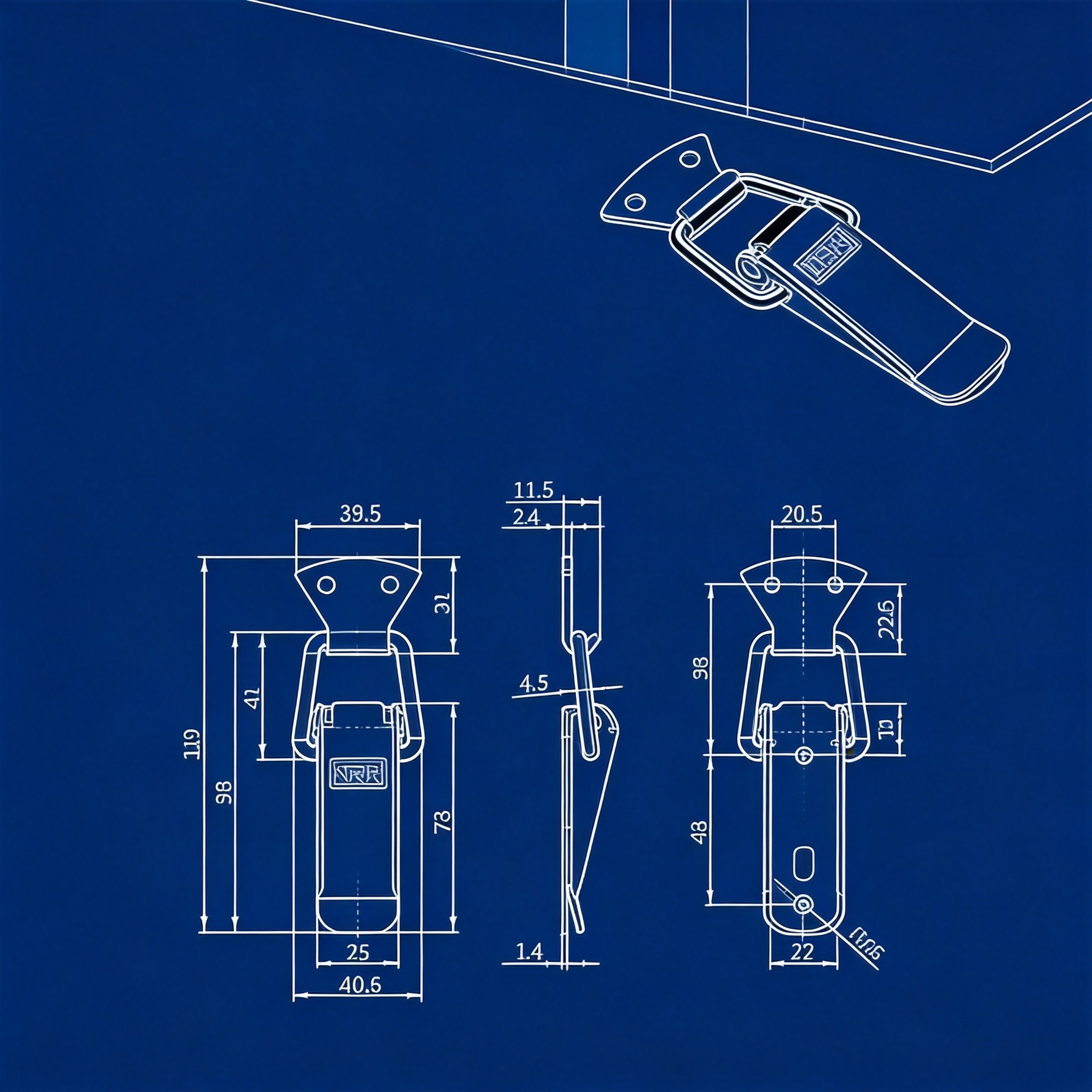
Linear dimensions measure straight-line distances between two points. They appear as lines with arrowheads at each end, extending from extension lines off the part outline. A butterfly latch drawing, for example, might show a body width of 96 mm and a hook reach of 38 mm.
Diameter and radius dimensions identify circular features. Diameter marks use the symbol φ followed by the value (e.g., φ8 for an 8 mm mounting hole). Radius marks use R (e.g., R5 for a 5 mm corner radius). These matter when you drill mounting holes or design case cutouts.
Angular dimensions specify the angle between two lines or surfaces. They display as an arc with the degree value placed inside. On an adjustable draw latch, you may see a hook angle listed as 45°.
Pay attention to the datum reference. Drawings use letters like A, B, C to mark reference surfaces. All other dimensions relate back to these datums. If the datum is the mounting base of a latch, every height measurement starts from that surface.
Check dimensions against your case design early. A 2 mm mismatch on hole spacing can turn a functional latch into scrap.
2. Tolerance Symbols: What the Numbers Really Allow
No part is manufactured to an exact number. Tolerances define the acceptable range. Understanding them determines whether your hardware fits and functions.
General tolerances appear as a ± value next to a dimension. A mounting hole center distance listed as 80 ±0.2 mm means the actual distance can range from 79.8 to 80.2 mm. For case hardware, ±0.1 to ±0.5 mm is typical on critical dimensions per manufacturer catalog data.
GD&T symbols (Geometric Dimensioning and Tolerancing) go further. A feature control frame contains three elements: the geometric characteristic symbol, the tolerance value, and the datum references. Common GD&T symbols for hardware include:
- Flatness (parallelogram symbol): Controls how flat a mounting surface must be. Critical for latch bases that sit flush against the case panel.
- Position (crosshair symbol): Controls where a hole center falls within a tolerance zone. Keeps mounting holes aligned across a batch.
- Perpendicularity (inverted T symbol): Ensures a surface is 90° to a datum. Matters for hinge leaves that must sit square.
A tolerance stack-up analysis is essential when multiple parts mate together. If the latch hook has a ±0.3 mm tolerance and the catch plate has a ±0.3 mm tolerance, the combined deviation can reach 0.6 mm. That gap can cause rattling or failure to engage.
Buyers often skip tolerance review. That is a costly mistake. A latch that is 0.5 mm too wide will not slot into your case cutout. A hook reach 0.4 mm short will not reach the catch.
3. Material Callouts: Decoding the Grade
Material callouts sit in the title block or in notes on the drawing. They specify the exact alloy or grade. Getting this wrong means your hardware corrodes, bends, or breaks under load.
Common material codes for case hardware:
- SUS304: Austenitic stainless steel, 18% chromium, 8% nickel. The standard for corrosion resistance in industrial cases. Used in NRH Box Hardware latch series 5101, 5102, and 5103.
- SUS201: Lower-nickel austenitic stainless. Lower cost, adequate for indoor or dry environments. Found in economy latch variants.
- SUS316: Molybdenum-added stainless. Superior salt-spray resistance. Used in marine and medical case applications.
- FE (Carbon steel): High strength, lower cost. Requires surface treatment to prevent rust. Common in zinc-alloy case locks and heavy-duty latches.
- Zinc alloy (ZN): Used for die-cast lock bodies and decorative handles. Good detail reproduction but lower tensile strength than steel.
The title block lists material, surface treatment, and sometimes hardness. Cross-reference the material callout with your operating environment. SUS304 works for most indoor and sheltered outdoor cases. SUS316 is the right pick for saltwater exposure. Carbon steel with proper plating handles high-load indoor applications at lower cost per manufacturer catalog data.
4. Surface Finish Notations: Reading the Roughness
Surface finish affects both function and appearance. A rough mounting surface prevents proper sealing. A polished exterior finish defines the product look.
Drawings use two main notation systems:
Ra (Roughness Average) is the most common metric. Lower Ra values mean smoother surfaces. Typical values for case hardware:
- Ra 0.4–0.8 μm: Mirror-polish or bright-finish handles and locks
- Ra 1.6 μm: Standard machined surfaces, hinge pins
- Ra 3.2–6.3 μm: As-cast or blasted surfaces, interior bracket faces
Surface treatment codes tell you what process was applied. Common codes include:
- ZG (Vibratory grinding): Produces a uniform satin finish on stainless parts. Reduces surface burrs and sharp edges.
- LG (Bright polish): Mirror-like finish on handles and visible hardware. Ra typically below 0.4 μm.
- CR (Chrome plating): Hard, bright surface over carbon steel. Improves wear and corrosion resistance.
- ZL (Zinc plating): Basic corrosion protection for carbon steel parts. Often appears with a clear or yellow chromate passivation.
- BK/BK2/BK3/BK4 (Black finishes): Various black coatings including electrophoretic deposition (e-coat) and black oxide. Used for low-visibility hardware on dark cases.
- PS (Sand blasting): Matte texture, uniform gray appearance. Hides fingerprints and minor scratches.
Match the surface finish to your case requirements. An outdoor transit case needs a corrosion-resistant plating (CR or ZG on stainless). A display case demands a bright finish (LG or CR) for visual appeal.
5. Verification Guide: How to Confirm Hardware Meets Your Specs
Reading the drawing is half the job. The other half is confirming the delivered hardware matches it. Follow this verification checklist.
Step 1: Check critical dimensions with calipers. Measure the three dimensions that control fit: mounting hole spacing, body width, and hook or latch reach. Compare each against the drawing. Flag anything outside the stated tolerance.
Step 2: Verify tolerances with a sample batch. Measure 10 parts from a production run. Calculate the mean and standard deviation. If the mean drifts beyond the tolerance midpoint, the process is shifting. Catch this early before the whole batch drifts out of spec.
Step 3: Confirm material grade. Request a material test report (MTR) from the supplier. The MTR lists chemical composition and mechanical properties. Verify that chromium and nickel content matches the callout (e.g., 18% Cr and 8% Ni for SUS304). A portable XRF analyzer can also spot-check material grade on incoming parts.
Step 4: Review surface finish against the spec. Use a surface roughness tester to measure Ra values. Visually inspect plating adhesion with a cross-hatch tape test. Check for plating skips, rust spots, or inconsistent texture.
Step 5: Cross-reference load ratings. Compare the drawing’s load specification against your application requirement. A draw latch rated for 35 kg holding force per manufacturer catalog data does not belong on a 50 kg case door. Add a 1.5x safety margin for dynamic loads during transport.
Document every verification step. A simple spreadsheet with part number, measured value, drawing value, and pass/fail status catches problems early and gives you leverage with suppliers.
Common Drawing Errors to Watch For
Even professional drawings contain mistakes. Look for these red flags:
- Missing tolerances: If a dimension has no tolerance, you have no acceptance criteria. Request clarification.
- Inconsistent units: Some drawings mix millimeters and inches. Confirm the unit system before you start measuring.
- Outdated revisions: Check the revision letter in the title block. Build tooling from an old revision and you remake parts.
- Unclear datum references: Without defined datums, inspectors measure from different surfaces and get different results.
Catching these errors before production saves time and money. A single drawing revision caught early prevents weeks of rework.
FAQ
What does φ mean on a hardware drawing?
φ indicates a diameter dimension. φ8 means the hole or circular feature is 8 mm in diameter. Always check if the tolerance applies to this value.
How do I read a GD&T feature control frame?
Read left to right: the geometric symbol comes first, then the tolerance value (with any modifier like M for maximum material condition), then the datum references. A frame showing the position symbol, 0.2, and datum A means the feature must fall within a 0.2 mm zone relative to datum A.
What is the difference between Ra and Rz surface finish values?
Ra is the arithmetic average of surface height deviations. Rz is the average of the five highest peaks and five lowest valleys. Rz values run roughly 4–7 times higher than Ra for the same surface. Always confirm which metric the drawing specifies.
What tolerance is standard for case hardware mounting holes?
Mounting hole positions typically carry ±0.2 to ±0.5 mm tolerances. Hole diameters use H13 or H14 fit grades, which allow ±0.1 to ±0.3 mm depending on size.
How do I verify SUS304 versus SUS201 material without lab equipment?
A portable XRF (X-ray fluorescence) analyzer gives a quick chemical readout in seconds. Without one, check the MTR from the supplier. Visual inspection cannot reliably distinguish the two grades.
Why does my latch not fit even though dimensions match the drawing?
Check tolerance stack-up. Each individual dimension may be in spec, but cumulative deviations across multiple features can cause interference. Also verify that your case cutout drawing uses the same datum references as the hardware drawing.
What surface finish do I need for outdoor case hardware?
Outdoor hardware requires both a corrosion-resistant base material and a protective surface treatment. SUS304 with vibratory grinding (ZG) or chrome-plated carbon steel (CR) are the most common specifications. Avoid bare carbon steel and zinc-only plating for extended outdoor exposure.
Can I use a drawing from one manufacturer to source from another?
You can use it as a reference, but expect dimensional and tolerance differences. Each manufacturer defines their own datums and tolerance schemes. Always request and review the actual drawing from the specific supplier before committing.
Need help choosing? Contact our engineering team for drawing interpretation support and hardware selection guidance.