

The Ultimate Guide to Toggle Latches: Over-Center Mechanisms, Engineering Principles, and Selection
Quick Answer: A toggle latch is a mechanical fastener that uses an over-center linkage system to generate high clamping force and resist vibration-induced opening. Unlike friction-based catches, the geometric lock of a toggle latch becomes stronger under load. NRH offers 8 distinct toggle latch series covering spring-loaded, hook-type, draw, long-type, double-spring, adjustable, safety, and butterfly locking designs – with material options from 304 stainless steel to zinc-plated steel, and load capacities from 30kg to 750N.
Have you ever opened a transit case and found the latch unlatched – without anyone touching it? That is the signature failure of a friction-based latch: magnetic catches, spring clips, and simple hooks all share the same weakness. They rely on friction or spring force. Vibration from transport slowly works them open. The latch does not fail suddenly. It creeps open over thousands of micro-vibrations until one day – the case pops open during transit. An over-center toggle latch solves this problem at the mechanical level. Not with stronger springs. Not with thicker material. With geometry that makes the latch stronger when pulled.
Applicable Buyers
This guide is for case builders, product designers, engineers, and procurement professionals selecting toggle latches for flight cases, industrial enclosures, military containers, medical equipment, insulation containers (including round insulated buckets with lids), and heavy-duty transit cases. NRH offers a complete range of toggle latch solutions – this article covers the over-center engineering principle, material selection, and a comprehensive guide to each product series based on real NRH product data.
Key Finding: The over-center mechanism is the defining engineering feature of a toggle latch. When the handle is pushed past the dead-center point, the linkage enters a stable geometric lock that resists opening forces – the latch becomes stronger under load. Vibration, impact, and thermal cycling do not loosen an over-center latch because the lock is geometry-based, not friction-dependent. NRH manufactures eight toggle latch series across 304 stainless steel, 201 stainless steel, and zinc-plated steel, with load capacities ranging from 30kg to 750N, serving applications from flight cases to military wood crates to round insulated containers.
Toggle latches are among the most widely used mechanical fasteners in industrial case hardware. Their ability to generate high clamping force, resist vibration, and provide tool-free operation makes them essential for flight cases, military containers, medical equipment enclosures, and industrial machinery guards. But not all toggle latches are created equal. Understanding the over-center engineering principle – and knowing which series fits which application – is the difference between a latch that stays locked for decades and one that fails on the first transport.
What Is a Toggle Latch?
A toggle latch is a mechanical fastener that uses a lever and linkage system to draw two panels together and hold them securely. The defining feature is the over-center mechanism – a geometric arrangement where the linkage passes beyond a straight-line (dead center) position and locks into a stable state.
Toggle latches are also known as:
- Over-center latches
- Draw latches (a subset)
- Clamping latches
- Toggle clamps (for industrial fixturing applications)
Toggle Latch vs Draw Latch: All NRH toggle latches are draw latches – they draw two panels together. “Draw latch” describes the function (drawing panels together); “toggle latch” describes the mechanism (over-center linkage). All 8 NRH series use the over-center principle, making them both toggle latches and draw latches.
Unlike spring clips, magnetic catches, or friction-based fasteners, a toggle latch does not rely on friction to stay closed. The over-center geometry creates a self-retaining lock that actually increases holding force when tension is applied to the panels.
The Over-Center Mechanism: Engineering Principles
The over-center mechanism is the core engineering principle that makes toggle latches superior for vibration-prone and high-load applications. Understanding how it works is essential for proper selection.
How the Over-Center Geometry Works – Visualized
The diagrams below show the three critical states of a toggle latch linkage:
| State 1: Open | State 2: Dead Center (Critical Point) | State 3: Locked (Over-Center) |
|---|---|---|
| Panel Linkage Handle UNSTABLE |
Panel Linkage Handle DEAD CENTER (Unstable equilibrium) |
Panel Linkage Handle LOCKED (Stable equilibrium) |
| Open position Linkage is angled. Panel can separate freely. |
The tipping point All pivots align in a straight line. Any force could send it either way. |
Over-center locked Handle pushed past dead center. Panel pull forces the latch TIGHTER. |
Three states of the over-center linkage:
- State 1 – Open: The linkage is angled. The panel can separate freely. Any pulling force opens the latch further.
- State 2 – Dead Center (The Tipping Point): All pivot axes align in a straight line. This is the critical point. The mechanism is in unstable equilibrium – the smallest force in either direction determines whether the latch opens or locks. In a properly designed latch, the operator provides this force by pushing the handle past this point.
- State 3 – Over-Center Locked: The handle has been pushed slightly beyond the dead-center line. The panel pulling force now acts with the linkage, not against it. The latch becomes self-retaining – pulling the panels apart actually forces the latch deeper into its locked position.
The over-travel distance past dead center is small – typically 1° to 3° in a well-designed toggle latch. This small angle is deliberate. Too little over-travel and the mechanism sits too close to the tipping point, vulnerable to vibration. Too much over-travel and the operator cannot release the latch with one hand.
The Physics of Holding Force – The Toggle Formula
The holding force of an over-center latch follows the toggle force formula – the fundamental equation that governs how much clamping force a toggle latch can generate from a given hand input:
Fhold = Fhand × (Lhandle / Lcoupler) × (1 / tan θ)
Where:
- Fhold = the clamping force applied to the panels (N or kg)
- Fhand = the force the operator applies to the handle (N)
- Lhandle = the effective lever arm length of the handle (mm)
- Lcoupler = the length of the coupler link (mm)
- θ (theta) = the angle between the coupler link and the dead-center line at the locked position
What this formula tells us:
- Mechanical advantage: The ratio (Lhandle / Lcoupler) multiplies the hand force. A longer handle relative to the coupler link produces greater clamping force.
- The 1/tan θ term: This is where the over-center magic happens. As θ approaches 0° (closer to dead center), 1/tan θ approaches infinity. The holding force theoretically becomes infinite at exactly dead center.
- In reality: Friction, link flex, and pivot clearance reduce the theoretical force by 40-60%. This is why well-designed latches use precision pivots and rigid links – to minimize these losses.
- The trade-off: A smaller θ (closer to dead center) produces higher holding force but makes the latch more sensitive to vibration. A larger θ reduces holding force but makes the latch more stable. The optimal θ is typically 1° to 3°.
What this formula explains:
- Why a toggle latch can hold far more than the operator’s hand force
- Why the latch becomes stronger when the panels pull apart – the pulling force reduces θ, increasing the 1/tan θ term
- Why dead-center alignment is the critical design parameter in every toggle latch
Engineering Calculation Example: NRH 5104-56 Holding Force
Using the toggle formula with NRH 5104-56 data:
- Estimated hand force (Fhand): 50 N
- Handle length ratio (Lhandle / Lcoupler): ~3.2
- Angle θ at locked position: ~2°
- Fhold = 50 × 3.2 × (1 / tan 2°) = 50 × 3.2 × 28.6 = 4,576 N (theoretical)
- With 50% efficiency loss (friction, pivot clearance): ~2,288 N actual holding force
This explains why a 21g latch (NRH 5104-56) can securely hold heavy flight case lids during transport vibration. The over-center geometry multiplies hand force by over 45x at the panel.
Why Vibration Cannot Shake an Over-Center Latch Open
Vibration causes two failure modes in non-over-center latches: progressive creep and resonance unlocking.
Progressive creep occurs when cyclic vibration delivers small impulses that gradually shift a friction-dependent catch toward open. A spring clip on a toolbox may hold firm for weeks – then thousands of micro-vibrations during transport shift the clip past its friction threshold, and the box pops open. There is no single dramatic event – just a slow march toward failure.
Resonance unlocking occurs when vibration frequency matches the natural frequency of the latch-spring system. The catch oscillates with increasing amplitude until it crosses the release point.
An over-center mechanism defeats both modes. For progressive creep: there is no incremental loosening because the latch is not held by friction. The locked position is a stable equilibrium – small displacements are self-correcting. For resonance: the effective spring constant of the locked linkage is extremely high (the 1/tan θ term), so the natural frequency sits far above any environmental vibration frequency. The latch simply does not resonate at operating frequencies.
This is why over-center toggle latches are standard on military cases, flight cases, and equipment enclosures subject to transport vibration.
Industry Standard Reference: Over-center toggle latches are widely specified in MIL-STD-810 (Environmental Engineering Considerations and Laboratory Tests) for transport case hardware. The standard requires hardware to withstand random vibration profiles up to 50 Hz at accelerations exceeding 7.7 g RMS without loosening. Over-center geometry latches consistently pass these tests because the lock is geometric, not friction-based. NRH toggle latches are designed to meet these demanding military-grade vibration requirements.
Why Choose an Over-Center Toggle Latch?
1. Superior Vibration Resistance
Toggle latches stay locked under vibration that would shake a magnetic catch, spring clip, or friction latch loose. The geometric lock does not rely on friction that can wear or creep. This is why over-center latches are specified for military, aerospace, and transport applications.
2. High Clamping Force
The toggle mechanism multiplies hand force through mechanical advantage. A small amount of operator effort produces substantial clamping pressure – ideal for compressing gaskets, sealing enclosures, and preventing panel rattle.
3. Tool-Free Operation
Toggle latches open and close with one hand – no tools required. This is critical for applications requiring frequent access, such as equipment maintenance, field servicing, and rapid deployment cases.
4. Adjustability
Many toggle latch series offer adjustable hooks or threaded draw lengths. This allows the operator to fine-tune clamping force for different panel thicknesses, gasket compression, or thermal expansion.
5. Secure Locking Options
Models with lock holes accept padlocks for security. Padlockable latches are used in transit cases, cargo containers, and any application requiring tamper resistance.
NRH Toggle Latch Series – Complete Specifications
NRH manufactures eight distinct toggle latch series, each optimized for specific applications, load requirements, and environments. The following sections detail each series with representative models and specifications based on actual NRH product data.
Series Comparison at a Glance
| Series | Type | Material Options | Load Capacity | Lock Hole | Spring | Sizes | Key Feature |
|---|---|---|---|---|---|---|---|
| 51 | Spring-loaded | 304 SS / 201 SS / Fe | 750N | Optional | Single | L / M / S / Mini | Spring return |
| 52 | Hook-type | 304 SS / Fe | 30kg | No | No | Standard | Hook engages round edges |
| 53 | Draw latch | 304 SS / Fe | 45kg | Yes | No | L / M / S | Padlockable |
| 54 | Long-type | Fe | 40kg | No | No | L / M / S | Extended reach |
| 55 | Dual-spring | 304 SS / Fe | 30kg | Optional | Dual | L / S | Dual spring return |
| 56 | Adjustable | 304 SS / Fe | 490N | Optional | Threaded | L / M / S | Threaded adjustment |
| 58 | Safety | 304 SS | 441N | No | No | L / S | Secondary safety lock |
| 63 | Butterfly | 304 SS | 588N | Optional | No | Standard | Symmetrical force distribution |
51 Series – Spring Loaded Toggle Latches
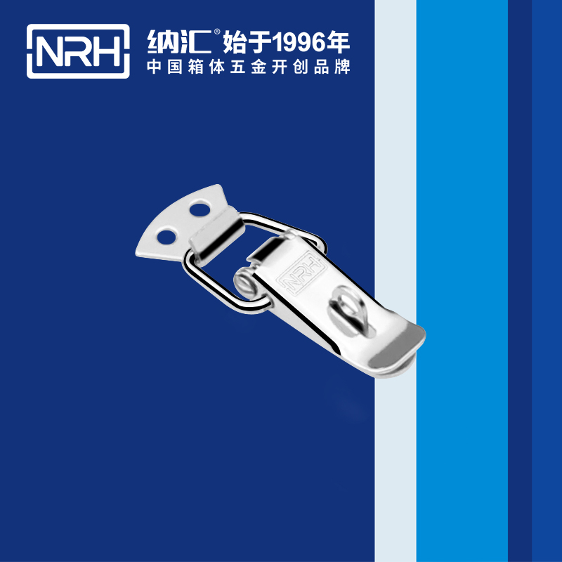
Series characteristics: The 51 series features an integrated spring that assists handle return and maintains consistent tension across the latch stroke. Available in large, medium, small, and miniature sizes with options for 201 stainless steel, 304 stainless steel, and zinc-plated steel. Locking and non-locking versions available.
Key applications: Flight cases, instrument cases, equipment enclosures where spring-assisted operation improves user experience.
Representative model: 5104-56
| Parameter | Specification |
|---|---|
| Model | 5104-56 |
| Material | 304 stainless steel |
| Surface finish | Vibratory ground |
| Weight | 21 g |
| Tensile load | 750 N |
| Dimensions (L x W) | 56.5 x 41.5 mm |
| Lock hole | Not available |
| Spring | Yes (single spring) |
52 Series – Hook Type Toggle Latches
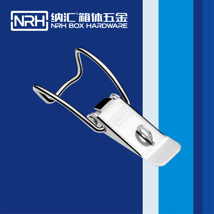
Series characteristics: The 52 series uses a hook design that engages the edge of a panel or circular object. The hook wraps around the rim, providing secure engagement without requiring a latch plate or strike. Ideal for round objects, insulated containers, and applications where the latch must grip a curved or irregular edge. Available in zinc-plated steel and 304 stainless steel.
Key applications: Insulated containers (including round insulated buckets with lids), thermal containers, drum lids, and cylindrical enclosures.
Representative model: 5202-102K
| Parameter | Specification |
|---|---|
| Model | 5202-102K |
| Material | 304 stainless steel |
| Surface finish | Vibratory ground |
| Weight | 60 g |
| Load capacity | 30 kg |
| Lock hole | Not available |
| Design | Hook-type, suitable for circular edges |
53 Series – Draw Latches (Non-Spring)
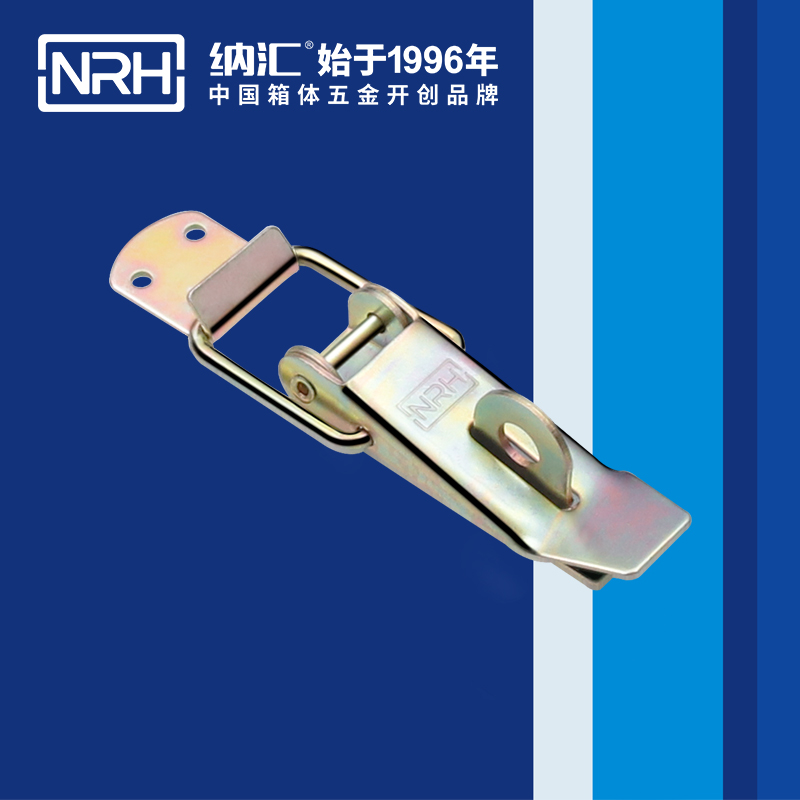
Series characteristics: The 53 series is a classic draw latch design – no spring mechanism, just pure over-center geometry. Available in large, medium, and small sizes with lock holes standard. Zinc-plated steel and 304 stainless steel options. The heavy-duty construction and padlock capability make this series suitable for security-sensitive applications.
Key applications: Industrial enclosures, machinery guards, access panels requiring padlock security, and cases where spring assistance is not needed.
Representative model: 5301-112K-KS-FE-CL
| Parameter | Specification |
|---|---|
| Model | 5301-112K-KS-FE-CL |
| Material | Zinc-plated steel |
| Surface finish | Zinc-chromate plated |
| Weight | 119 g |
| Load capacity | 45 kg |
| Lock hole | Yes |
| Spring | No |
| Hook type | Long curved hook |
54 Series – Long Type Toggle Latches
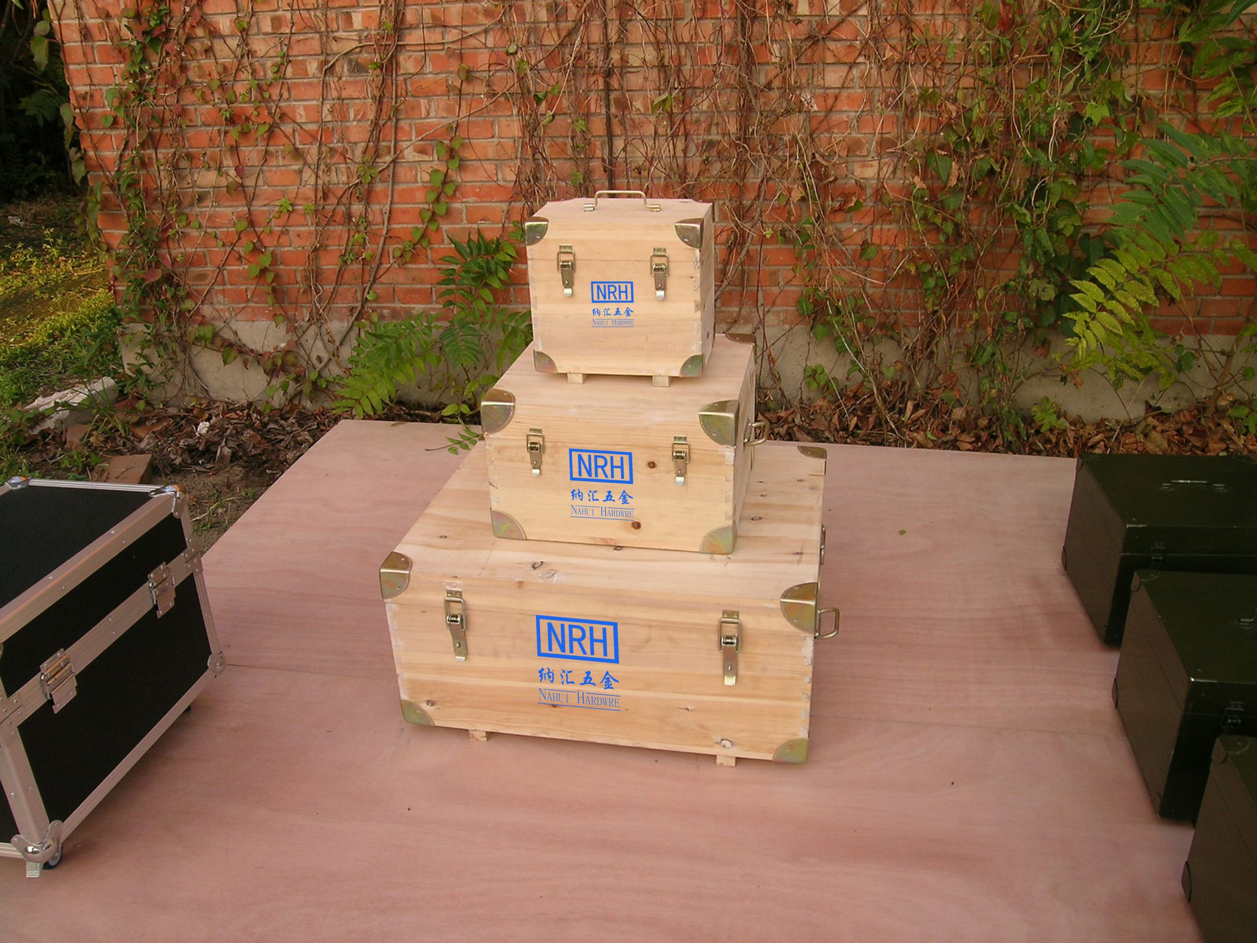
Series characteristics: The 54 series features an extended body length for applications requiring greater reach or deeper panel engagement. Designed specifically for military wood crates and large transit containers. Available in large, medium, and small sizes with zinc-plated steel construction. No lock hole. No spring mechanism – pure over-center draw action.
Key applications: Military wood crates, export packing cases, large wooden boxes, and heavy-duty transit containers where extended reach is required.
Representative model: 5401-122-KS-FE-CL
| Parameter | Specification |
|---|---|
| Model | 5401-122-KS-FE-CL |
| Material | Zinc-plated steel |
| Surface finish | Zinc-chromate plated |
| Weight | 214 g |
| Load capacity | 40 kg |
| Lock hole | No |
| Spring | No |
| Design | Long body, military wood crate application |
55 Series – Double Spring Toggle Latches
Series characteristics: The 55 series features dual springs for enhanced return force and handle positioning. Available in large and small sizes with lock hole options. Dual spring design ensures positive handle positioning in both open and closed states. Available in zinc-plated steel and 304 stainless steel.
Key applications: High-cycle applications, equipment enclosures with frequent access, heavy-duty cases requiring spring assistance.
Representative model: 5505-75K-S04-ZG
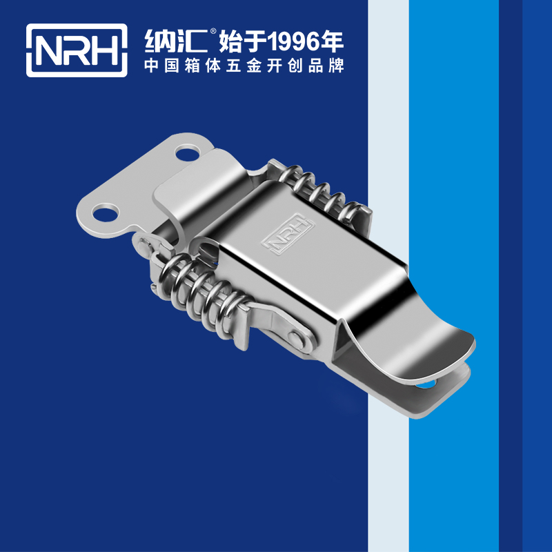
| Parameter | Specification |
|---|---|
| Model | 5505-75K-S04-ZG |
| Material | 304 stainless steel |
| Surface finish | Vibratory ground |
| Weight | 79 g |
| Load capacity | 30 kg |
| Lock hole | Yes |
| Spring | Yes (dual spring) |
56 Series – Adjustable Toggle Latches
Series characteristics: The 56 series features a threaded adjustment mechanism that allows fine-tuning of the clamping distance. Ideal for applications with varying panel thicknesses, gasket compression requirements, or thermal expansion. Available in small, medium, and large sizes with lock hole options. Zinc-plated steel and 304 stainless steel.
Key applications: Enclosures with gaskets requiring precise compression control, applications with varying panel thicknesses, thermal cycling environments.
Representative model: 5608-70K-S04-ZG
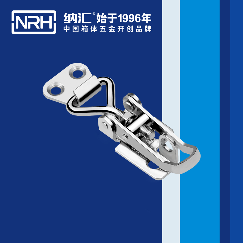
| Parameter | Specification |
|---|---|
| Model | 5608-70K-S04-ZG |
| Material | 304 stainless steel |
| Surface finish | Vibratory ground |
| Weight | 51 g |
| Tensile load | 490 N |
| Lock hole | Yes |
| Adjustment range | 70-82 mm (threaded adjustment) |
58 Series – Safety Toggle Latches
Series characteristics: The 58 series incorporates a safety lock mechanism that prevents accidental opening. The secondary latch must be released before the main handle can be operated. Available in large and small sizes with 304 stainless steel construction. The safety mechanism makes this series ideal for high-risk environments.
Key applications: Medical equipment requiring accidental-opening prevention, high-vibration environments, safety-critical enclosures, hazardous area equipment.
Representative model: 5808-98S-S04-ZG
| Parameter | Specification |
|---|---|
| Model | 5808-98S-S04-ZG |
| Material | 304 stainless steel |
| Surface finish | Vibratory ground |
| Weight | 65 g |
| Tensile load | 441 N |
| Lock hole | Not available |
| Design | Safety lock mechanism |
63 Series – Butterfly Locking Latches
Series characteristics: The 63 series butterfly locking latch features a symmetrical butterfly handle design that distributes force evenly across two locking points. Available with lock hole options in 304 stainless steel. The butterfly design provides excellent ergonomics and visual symmetry for premium case applications.
Key applications: Medical equipment cases, premium flight cases, display cases, and enclosures where aesthetics and balanced force distribution are important.
Representative model: 6324-74
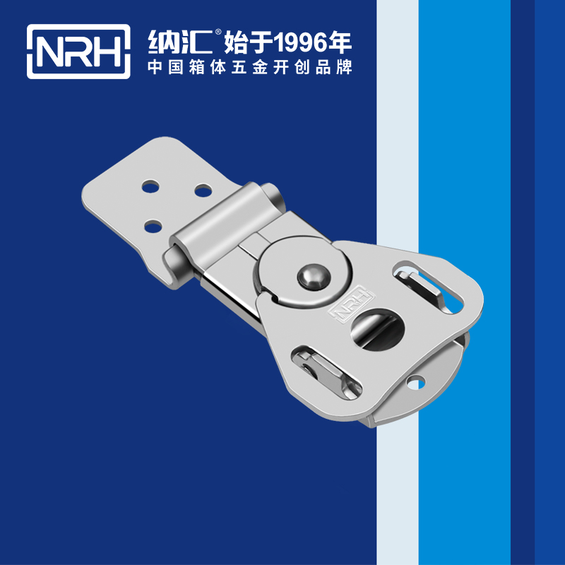
| Parameter | Specification |
|---|---|
| Model | 6324-74 |
| Material | 304 stainless steel |
| Surface finish | Vibratory ground |
| Weight | 97 g |
| Tensile load | 588 N |
| Lock hole | Not available |
| Design | Butterfly locking, symmetrical force distribution |
Material and Finish Options
NRH toggle latches are manufactured in three material grades and multiple surface finishes to suit different environmental and cost requirements.
| Material | Finish Options | Best Environment | Typical Series |
|---|---|---|---|
| 304 Stainless Steel | Vibratory ground (ZG) | Outdoor, marine, medical, food processing | 51, 52, 55, 56, 58, 63 |
| 201 Stainless Steel | Vibratory ground | Indoor applications, cost-sensitive | 51 |
| Zinc-Plated Steel | Zinc-chromate plated (CL) | Indoor industrial, wood crates | 53, 54 |
Finish explanation:
- Vibratory ground (ZG): A mechanical tumbling process that produces a uniform satin texture. Hides fingerprints and minor scratches. Standard on NRH stainless steel toggle latches.
- Zinc-chromate plated (CL): A yellow-zinc plating that provides corrosion resistance at a lower cost point. Standard on NRH steel toggle latches.
Selection Guide: Which Toggle Latch for Your Application?
Use the following framework to select the right NRH toggle latch series for your specific application requirements.
Step 1: Identify Your Application Environment
| Environment | Recommended Material | Recommended Series |
|---|---|---|
| Outdoor / Marine / Salt spray | 304 Stainless Steel | 51, 52, 55, 56, 58, 63 |
| Indoor industrial / Workshop | Zinc-plated steel or 304 SS | 53, 54 |
| Medical / Cleanroom | 304 Stainless Steel | 51, 58, 63 |
| Food / Beverage | 304 Stainless Steel | 52 (insulated containers), 51 |
Step 2: Determine Load Requirements
Estimate the maximum load the latch will experience in service – including static load, dynamic load, and vibration. Select a latch with a tensile load or load capacity that exceeds your application requirements by a safety factor of at least 2x.
| Load Range | Recommended Series | Example Model |
|---|---|---|
| Up to 30kg / 294N | 52, 55 | 5202-102K (30kg), 5505-75K (30kg) |
| 40-45kg / 392-441N | 53, 54, 58 | 5301-112K (45kg), 5401-122 (40kg), 5808-98S (441N) |
| 490-588N | 56, 63 | 5608-70K (490N), 6324-74 (588N) |
| 750N | 51 | 5104-56 (750N) |
Step 3: Consider Special Features
- Spring assistance required? -> 51 series (single spring) or 55 series (dual spring)
- Lock hole / padlock required? -> 53 series (standard), 55 series, 56 series (options available)
- Adjustable clamping distance needed? -> 56 series (threaded adjustment)
- Safety lock / accidental opening prevention? -> 58 series
- Hook engagement for circular objects? -> 52 series
- Extended reach for deep panels? -> 54 series
- Symmetrical force distribution? -> 63 series (butterfly design)
Installation and Adjustment Guide
Proper installation and adjustment are essential for achieving the full performance of an over-center toggle latch. A correctly installed latch provides consistent clamping force, resists vibration, and operates smoothly for thousands of cycles. An incorrectly installed latch – even with the right product – will fail prematurely.
General Installation Guidelines
- Mounting hole alignment: Ensure all mounting holes are aligned with the latch base plate. Misalignment creates binding that increases operating force and accelerates wear.
- Fastener selection: Use rivets for permanent installations where the latch will not be removed. Use machine screws with lock nuts for removable installations where service access is required.
- Fastener torque: Tighten fasteners to the manufacturer’s recommended torque. Over-tightening can deform the latch base or strip threads. Under-tightening allows the latch to shift under load.
- Strike plate positioning: The strike plate (or hook engagement point) must align with the latch hook when closed. Misalignment causes uneven load distribution and increases wear on the pivot points.
- Test operation: After installation, cycle the latch 10-20 times. Verify smooth operation and full engagement. A properly installed latch should click into the locked position with a positive feel.
Adjusting the 56 Series (Threaded Adjustment)
The 56 series features a threaded adjustment mechanism that allows fine-tuning of the clamping distance. Follow these steps to achieve the optimal setting:
- Determine the required draw distance: Measure the distance between the latch mounting surface and the strike point when the panel is closed. The adjustment range on the 5608-70K is 70-82 mm. Select the setting that matches your panel gap plus desired gasket compression.
- Adjust the threaded hook: Turn the threaded hook in or out to achieve the desired draw distance. Turning the hook inward (clockwise) reduces the draw distance and increases clamping force. Turning it outward (counterclockwise) increases the draw distance and reduces clamping force.
- Test the adjustment: Close the latch and check the clamping feel. The handle should close with moderate effort – not too loose (no clamping force) and not too tight (requires excessive force to close).
- Lock the adjuster: Once the optimal setting is found, tighten the locknut to secure the adjustment. Vibration can rotate the threaded hook if the locknut is not properly secured.
- Re-test after locknut torque: Cycle the latch several times after tightening the locknut to verify the adjustment has not shifted.
Common Installation Mistakes to Avoid
- Over-tightening fasteners: Deforms the latch base and increases friction at pivot points.
- Misaligned strike plate: Creates side-loading on the hook and linkage, causing premature wear.
- Incorrect draw adjustment: Too little draw provides insufficient clamping force. Too much draw makes the latch difficult to close and can overstress the linkage.
- Missing locknuts: On adjustable models, failure to tighten the locknut allows the adjustment to change under vibration.
- Using the wrong fastener type: Self-tapping screws in metal panels without pilot holes can strip or crack the panel. Use appropriate fasteners for the panel material.
Real-World Application Examples
The following examples illustrate how specific NRH toggle latch series solve real engineering challenges in the field.
Application Example 1: Flight Case Manufacturer
A flight case manufacturer producing touring cases for professional audio equipment needed a latch that could withstand thousands of open-close cycles per year while maintaining secure closure during transport by truck and air freight. The cases use 9mm plywood with aluminum edges, and the latch must sit flush with the panel surface to avoid snagging on conveyor belts and stacking equipment.
Challenge: The previous spring-loaded latch used by the manufacturer was failing at the pivot point after approximately 15,000 cycles. The spring tension would degrade, and the latch would no longer hold the case closed during transport.
Solution: The manufacturer switched to the NRH 51 series spring-loaded toggle latch. The 51 series offers:
- Spring-assisted return for convenient one-handed operation
- 750N tensile load capacity – sufficient for heavy audio equipment cases
- 304 stainless steel construction with vibratory finish for corrosion resistance in damp venue conditions
- Compact design that fits within the 9mm plywood panel thickness
Result: The new latches have exceeded 50,000 cycles on test fixtures with no measurable wear at the pivot points. The spring return maintains consistent tension, and the over-center geometry ensures the latch stays locked during transport vibration. The manufacturer has standardized on the 51 series across all touring cases.
Application Example 2: Insulated Container for Cold Chain Logistics
A cold chain logistics provider needed a latch for round insulated containers used to transport temperature-sensitive pharmaceuticals. The containers have a thick insulation layer (30-40mm) with a tight sealing gasket around the lid. The latch must engage the curved rim of the container without requiring a flat latch plate.
Challenge: Standard draw latches require a flat strike plate on the container body. The curved surface of the insulated container did not provide a flat mounting surface, and adding a strike plate would compromise the insulation integrity.
Solution: The provider selected the NRH 52 series hook-type toggle latch. The hook design wraps around the rim of the container, providing secure engagement without requiring a strike plate:
- Hook-type engagement eliminates the need for a flat latch plate
- 304 stainless steel construction resists corrosion from condensation and cleaning agents
- 30kg load capacity provides ample holding force for the insulated lid and gasket compression
- The over-center mechanism ensures the lid stays sealed during transport vibration
Result: The hook-type latches have proven reliable across thousands of cold chain shipments. The latches maintain consistent gasket compression, and the over-center geometry prevents lid opening during transport – even when containers are stacked three high on pallets.
Application Example 3: Military Wood Crate Manufacturer
A defense contractor manufacturing wooden ammunition crates for the military required a latch that could withstand rugged handling in field conditions. The crates have thick wooden walls (20mm+), and the latch must provide extended reach to engage the lid while remaining simple and field-serviceable.
Challenge: The contractor’s previous latch used a spring-loaded mechanism that failed in sandy and dusty environments. Spring jamming and corrosion shortened the service life, and field units did not have the tools or parts to repair them.
Solution: The contractor selected the NRH 54 series long-type toggle latch:
- Extended body length provides the reach required for thick wooden walls
- No spring mechanism – pure over-center geometry eliminates spring failure modes
- Zinc-plated steel construction provides corrosion resistance at a practical cost point
- Simple mechanical design allows field servicing with basic hand tools
Result: The 54 series latches have performed reliably in military field conditions, including desert and tropical deployments. The absence of spring components has eliminated the most common failure mode, and field units report the latches are easier to service than the previous design. The over-center geometry maintains secure closure even when crates are subject to rough handling and transport vibration.
Frequently Asked Questions (FAQ)
What is a toggle latch?
A toggle latch is a mechanical fastener that uses an over-center linkage system to draw two panels together and hold them securely. The over-center geometry creates a stable, self-retaining lock that resists vibration and opening forces without relying on friction.
What does “over-center” mean in a toggle latch?
Over-center means the linkage passes beyond the dead-center point – the position where all pivot axes align in a straight line. Past that point, the mechanism is in a stable locked state that resists opening forces rather than yielding to them. This is the defining engineering feature of a true toggle latch.
Does an over-center latch need a spring to stay closed?
No. The geometry provides retention. Springs (as found in the 51 and 55 series) are added for operator convenience – to assist handle return or maintain handle position – but the self-locking is a product of linkage geometry, not spring force.
Why do toggle latches resist vibration better than magnetic catches or spring clips?
Magnetic catches and spring clips rely on a friction-like holding force with a defined threshold. Vibration can exceed that threshold repeatedly, causing progressive creep toward open. An over-center latch has no friction threshold – the locked position is a geometric stable equilibrium that vibration cannot incrementally shift.
What is the difference between a toggle latch and a draw latch?
All over-center toggle latches are draw latches – they draw two panels together. Not all draw latches are over-center. A basic draw latch may rely on spring force or a secondary catch, not geometric self-locking. Always verify the over-center feature if vibration resistance is required.
What materials are available for NRH toggle latches?
NRH toggle latches are available in 304 stainless steel, 201 stainless steel, and zinc-plated steel. Surface finishes include vibratory ground (satin) for stainless steel and zinc-chromate plated for steel.
Can NRH toggle latches be padlocked?
Yes. Models with a lock hole in the handle or body accept standard padlocks. The 53 series (draw latches) and select 55 and 56 series models are available with lock holes. Check the specific model suffix – “K” often indicates a lock hole option.
What is the load capacity of NRH toggle latches?
NRH toggle latch load capacities range from 30kg (52, 55 series) to 750N tensile load (51 series). The 53 series offers 45kg capacity, 54 series offers 40kg, 58 series offers 441N, and 63 series offers 588N. Select based on your application requirements.
How do I adjust the clamping force on a 56 series latch?
The 56 series features a threaded adjustment mechanism. Turn the threaded hook in or out to adjust the clamping distance. The adjustment range on the 5608-70K is 70-82 mm. More thread engagement increases draw and clamping force. Always tighten the locknut after adjustment.
Which NRH toggle latch is best for military cases or wood crates?
The 54 series (long type) was specifically designed for military wood crates and export packing cases. The extended body length provides the reach needed for thick panel assemblies, and the zinc-plated steel construction offers durability at a practical cost point.
Can these latches be used on round containers like insulated buckets?
Yes. The 52 series hook-type toggle latches are specifically designed for round objects. The hook design wraps around the rim of round containers, insulated buckets, and similar cylindrical enclosures, providing secure engagement without requiring a flat latch plate.
Key Takeaways
- Over-center geometry is the defining feature of a true toggle latch – the latch becomes stronger under load, not weaker. The toggle formula Fhold = Fhand x (Lhandle / Lcoupler) x (1 / tan θ) explains this fundamental advantage.
- Vibration resistance is the primary advantage – over-center latches do not creep open under cyclic vibration like friction-dependent catches.
- NRH offers 8 distinct toggle latch series – 51 (spring), 52 (hook), 53 (draw), 54 (long), 55 (dual spring), 56 (adjustable), 58 (safety), and 63 (butterfly).
- 304 stainless steel provides maximum corrosion resistance for outdoor, marine, and medical applications. Zinc-plated steel offers cost-effective performance for indoor industrial use.
- Lock hole options are available on select models for padlock security.
- Threaded adjustment (56 series) allows fine-tuning of clamping distance for gasket compression and varying panel thicknesses.
- Hook-type design (52 series) is ideal for round containers and insulated buckets.
- Safety lock mechanism (58 series) prevents accidental opening in high-risk environments.
- Proper installation and adjustment are critical – a correctly installed latch provides reliable service for thousands of cycles. The 56 series adjustment range is 70-82 mm.
- Always verify the over-center feature – not all draw latches are over-center latches.
About NRH
NRH is a brand of Shanghai Nahui Hardware Products Co., Ltd., established in 1996 and headquartered in Shanghai, China. The company specialises in R&D and production of high-quality hardware fittings for cases and boxes – including toggle latches, handles, hinges, and corner protectors. NRH toggle latches are manufactured in 304 stainless steel, 201 stainless steel, and zinc-plated steel with multiple finish options, serving military, medical, aviation, industrial, and logistics applications worldwide.
All NRH toggle latch data presented in this guide is based on actual product specifications and marked “for reference only – not for tooling/mould creation”. For official engineering drawings, customisation enquiries, or bulk orders, please contact the NRH sales team directly.
For official engineering drawings, customisation enquiries, or bulk orders, please visit the NRH product pages or contact the sales team directly.